| |
|
| Available Services |
|
 |
|
|
|
Fiber Optic Modems
|
|
The industrial fiber optic networking product line of NSPI was established through the acquisitions of Apec Electronics in 1991 and the EOTec business of the 3M Company in 1994.
Over the years NSPI has continued to invest in the development of these products by adding new protocols, features and capabilities. NSPI was the first company to receive Factory Mutual (FM) hazardous area certification for fiber optic modems. In addition, we pioneered the development of Self-Healing Ring technology which provides high reliability, media redundant PLC/DCS communications (Patent #6,307,652). Recently, NSPI introduced the EOTec 2104 Ethernet Ring Switch which provides an economical solution to the combination of high performance ring redundancy with Ethernet communications. |
|
| EOTec 2000 series |
The EOTec 2000 Fiber optic modems are a family of modules designed to take traditional copper networks, convert them to fiber optic signals, and convert them back again. All modules fit on standard 35mm DIN rail and each has an integrated backplane. As a result, there is no separate backplane to purchase and no external wiring between modules. Simply attach each module to the DIN rail and slide them together until they mate to one another.
The EOTec 2000 series represents an extremely flexible and scalable solution to the problems often encountered when using copper to interconnect communication nodes. Both multi-mode and single-mode fiber optic links are supported. Options are available to support all the popular fiber optic connectors (ST, SMA, SC), providing users the ability to construct dependable and robust networks.
Problems such as ground loops, isolation and lightning strikes are eliminated with the EOTec 2000 fiber optic modems. Fiber optic communication links can also be extended over much greater distances and take on physical topologies not available with copper networks. For instance, star and self-healing ring topologies are impossible when using copper interconnects. These configurations are easily achievable with the EOTec 2000.
Inter-module communications and power distribution is handled by the internal EOTec 2000 BUS architecture to minimize external wiring.
Each node can support up to five (5) EIMs or OIMs to suite the application. The EOTec system allows the user to build a fiber optic system that supports several network topologies, including:
- Point-To-Point
- Daisy-chain
- Star
- Self healing ring
- Dual self healing ring
|
|
| EOTec 2000 application hints: |
- Each cluster can have a maximum of five communication modules (power supplies not included).
- Each cluster must have one (and only one) module set to Master (M). Any additional modules sharing a common backplane with the Master must be set to a numerical address (1, 2, 3 or 4). Numerical addresses cannot be repeated in a single cluster.
- When employing a self-healing ring configuration, the self-healing ring module is hardwired as Master. The electrical interface module must be set to “1” and the adjacent modules must be set to “2” and “3”.
- The default setting for the optical transmit power is “H” (high); this setting should not be adjusted unless an optical overdrive situation occurs.
- Pay attention to the terminations on the electrical interface modules. Modules without internal termination can be used anywhere along a copper segment. Modules with internal termination must be used at the end of copper segments only.
|
|
|
Constructing fiber optic communication nodes is very easy if the user keeps a few simple guidelines in mind. At a very minimum, every fiber optic node will require a power supply module (PSM), electrical interface module (EIM) and optical interface module (OIM).
|
|
|
| |
| Industrial
Fiber Optics |
|

click
to enlarge
|
Weed
Instrument is the world’s leading manufacturer
of Fiber Optic Networking Equipment for Industrial
Automation & Process Control applications.
- Over
three decades of experience in fiber optic networking
technology.
- Weed
Instrument offers the world’s largest selection
of fiber optic converters for PLC’s and
Distributed Control Systems.
- Weed
provides Fault Tolerant, Multidrop, and Fiber
Optic Communications solutions.
|
|
Options: |
- Industrial Ethernet, Profibus,
Modbus, Modbus Plus, ControlNet, DeviceNet,
Data Highway Plus, DH-485, Genius, Remote I/O,
RS232/484, Reliance R-Net
- Analog: 4-20mA, 0-10V
|
|
|
|
|
|
| Electrical
Interface Modules (EIMs) |
|
|
Connect to your PLC devices and/or fieldbus networked equipment.
The Electrical Interface Module (EIM) is connected to the copper communication link. The module receives signals from the copper link, conditions them and makes the signals available to the backplane for conversion. The EIM also accepts signals from the backplane and transmits the signals to the attached copper link. EIM part numbers always begin with 2C. It is important to select the correct EIM for the copper protocol being converted. For example, the 2C02 is the model which is compatible with GE Fanuc networks.
Key selection criteria:
- What communication protocol is being converted?
- What is the baud rate?
Selection guide: |
| Electrical Interface Modules |
|
| Model |
PLC / Fieldbus |
Data sheet (click to view) |
| 2C02 |
GE Fanuc Genius® |
2C02 |
| 2C07 |
Reliance R-Net & I/O |
2C07 |
| 2C10 |
RS-232 or RS-485, Half Duplex |
2C10 |
| 2C12 |
Allen-Bradley DH+® & Remote I/O |
2C12 |
| 2C14 |
Modicon® (S908) Remote I/O |
2C14 |
| 2C15 |
Allen Bradley DH-485 |
2C15 |
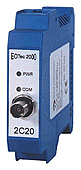
| 2C20 |
ControlNet® (view all ControlNet products) |
2C20 |
| 2C22 |
Profibus-DP |
2C22 |
| 2C23 |
Profibus-DP w/ Self-Healing Ring & 24VDC pwr |
2C23 |
| 2C29 |
Modicon® Modbus Plus® |
2C29 |
|
|
|
|
|
| Fiber
Optic Interface Modules (OIMs) |
|
|
Build a fiber based network using Single Mode or Multi-Mode Fiber Cables in a variety of topologies.
Key selection criteria:
- Is the fiber optic cable single mode or multi-mode?
- What types of connectors terminate the fiber optic cable? (ST or SMA)
- What is the total loss on the fiber optic link? (This number must be less than the optical budget of the OIM selected)
- Is fiber link monitoring desirable?
Selection Guide: |
Optical Interface Modules
without diagnostic output |
Optical Dynamic Range by fiber cable type |
Data Sheets (click to view) |
Connector |
Wavelength |
Mode |
200/
230µm |
62.5/
125µm |
9/125µm |
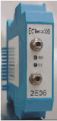
2E06 |
SMA |
850nm |
Multi |
21dB |
– |
– |
2E07 |
ST |
850nm |
Multi |
21dB |
12dB |
– |
2E09 |
ST |
1300nm |
Multi |
– |
12dB |
– |
2E10 |
ST |
850nm |
Multi |
23dB |
17dB |
– |
2E36 |
ST |
1300nm |
Single |
– |
– |
10dB |
2E46 |
ST |
1300nm |
Single |
– |
– |
16dB |
|
|
Optical Interface Modules
with diagnostic output |
Optical Dynamic Range by fiber cable type |
Data Sheets (click to view) |
Connector |
Wavelength |
Mode |
200/230µm |
62.5/125µm |
9/125µm |
2D06 |
SMA |
850nm |
Multi |
21dB |
– |
– |
2D07 |
ST |
850nm |
Multi |
21dB |
12dB |
– |
2D09 |
ST |
1300nm |
Multi |
– |
12dB |
– |
2D10 |
ST |
850nm |
Multi |
23dB |
17dB |
– |
2D36 |
ST |
1300nm |
Single |
– |
– |
10dB |
2D46 |
ST |
1300nm |
Single |
– |
– |
16dB |
Diagnostic output feature:
2Dxx optical modules provide a full diagnostic output (4-20mA). The output is internally powered and is proportional to the received optical power. The output can be monitored and processed continuously in order to insure the integrity of the fiber optic link. This is beneficial for critical applications such as subsea networking where degradation of the optical signals can be detected before a complete loss of communication occurs. An output less than 4mA indicates loss of optical signal. A pluggable screw terminal connection on the bottom front of the module provides easy access to the output signal. |
|
|
|
|
| Self-Healing Ring Module (SHRM) |
|

|
The use of fiber optic versus copper communications cable provides many advantages in industrial control applications. These include EMI/RFI immunity, the ability to easily run the cable through hazardous areas and long distance communications runs. Another important benefit is the ability to achieve media redundancy without incurring the cost of duplicate hardware systems.
By using the NSPI Self-Healing Ring solution, a critical system can achieve uninterrupted communications, even in the event of a failure in the fiber optic communications lines.
|
How the Self-Healing Ring works:
The NSPI Self-Healing Ring Module (SHR) provides fiber media redundancy when utilized in each node or drop of a fiber optic ring network. Data will always be routed on the shortest possible path to reduce propagation delay through the system. The SHR accomplishes this by creating a “virtual” break in the ring at the link farthest from the originating node. In the above illustration, if Node 1 is the originating node of a message, a virtual break will be created on the fiber link B or C (B is shown here). This virtual break is created on a packet by packet basis. Therefore, the network behaves as if it were in a Daisy Chain, preventing the delivery of the same packet to any node twice.
When a real fiber break actually does occur, the SHR devices detect the break and a virtual break is no longer created since the real fiber break has performed the function of putting the system into a Daisy Chain. The SHR automatically resets when the fiber path has been restored. Visible LED indicators in conjunction with relay contacts provide local and remote monitoring of the integrity of the fiber optic network.
Model 2C30 Series Self-Healing Ring module:
The 2C30 supports Self-Healing Ring applications in conjunction with any Electrical Interface Module (EIM) for GE Fanuc Genius®, Reliance R-Net & I/O, RS-232 or RS-485, Allen-Bradley DH+® & Remote I/O, Modicon® (S980) Remote I/O, Allen Bradley DH-485, or Modicon® Modbus Plus®. The Self-Healing Ring function is built into the Electrical Interface Module for Profibus (2C23). Consult our factory for ControlNet self healing ring applications. |
|
|
|
|
| Power Supply Modules (PSMs) |
|
|
Key selection criteria:
- Will AC or DC power be available at the installation site?
- Is redundancy required?
Module selection guide:
| Part no:
Data sheet (PDF) (click to view) |
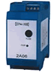
2A06 |
2A16 |
2A08 |
2A18 |
| Nominal input voltage: |
120/240 VAC at 50/60 Hz & 125 VDC |
120/240 VAC at 50/60 Hz & 125 VDC |
24VDC |
24VDC |
| Input current: |
250mA |
250mA |
400mA |
400mA |
| Input fuse: |
400mA
Slow-blow |
400mA
Slow-blow |
400mA
Slow-blow |
400mA
Slow-blow |
| Regulated output power: |
9VDC
1.1A Max. |
9VDC
1.1A Max. |
9VDC
1.1A Max. |
9VDC
1.1A Max. |
| Alarm relay: |
No |
Yes (1) |
No |
Yes (1) |
| Indicators: |
Power On
(Green LED) |
Power On
(Green LED) |
Power On
(Green LED) |
Power On
(Green LED) |
| Operating temperature: |
-40 to 85°C |
-40 to 85°C |
-40 to 85°C |
-40 to 85°C |
| Operating rel. humidity: |
0 to 90%
non-cond. |
0 to 90%
non-cond. |
0 to 90%
non-cond. |
0 to 90%
non-cond. |
| Height: |
3.9 inches |
3.9 inches |
3.9 inches |
3.9 inches |
| Width: |
1.8 inches |
1.8 inches |
0.9 inches |
0.9 inches |
| Depth: |
4.9 inches |
4.9 inches |
4.9 inches |
4.9 inches |
| CE mark |
Yes |
Yes |
Yes |
Yes |
| UL/cUL recognized component |
Yes |
Yes |
No |
No |
| UL/cUL listed for Class I, Div. 2 Hazardous Locations |
No |
No |
Yes |
Yes |
| FM approved for Class I, Div. 2 Hazardous Locations |
No |
No |
Yes |
Yes |
Note (1): Alarm contact – 1ea. Form C, 175VDC, 1 Amp continuous
|
|
|
|
|
| EOTec 2000 Fiber Optic Network Topologies |
The EOTec system supports multiple network topologies that allow users to distribute their PLC and fieldbus communications in configurations typically not supported by the native “copper” version of the same network. Use the links below to explore the possibilities: |
Optical Repeater
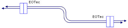
In this example, each EOTec 2000 node includes:
•Two (2) EOTec Fiber Optic Modules
•An EOTec Power Supply Module |
|
Point to Point configuration
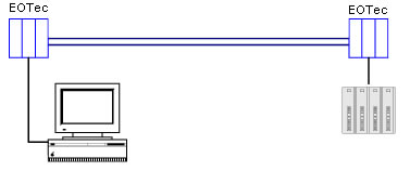
In this example, each EOTec 2000 node includes:
•One (1) EOTec Fiber Optic Modules
•One (1) or more EOTec Electrical Interface Modules
•An EOTec Power Supply Module |
|
Linear Drop / Daisy Chain configuration
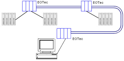
In this example, the EOTec 2000 nodes at the extreme ends of the network include:
•One (1) EOTec Fiber Optic Interface Modules
•One (1) or more EOTec Electrical Interface Modules
•An EOTec Power Supply Module
The other EOTec 2000 node(s) on the network include:
•Two (2) EOTec Fiber Optic Interface Modules
•One (1) or more EOTec Electrical Interface Modules
•An EOTec Power Supply Module |
|
Star configuration
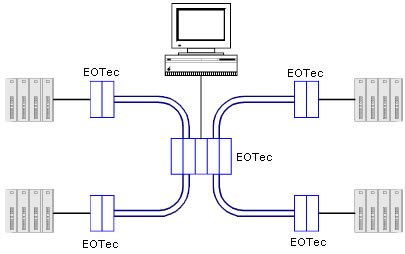
In this example, the central EOTec 2000 node includes:
Four (4) EOTec Fiber Optic Interface Modules, one (1) EOTec Electrical Interface Module, plus an EOTec Power Supply Module.
Each of the EOTec 2000 satellite nodes use one (1) EOTec Fiber Optic Interface Module, one (1) EOTec Electrical Interface Module, plus an EOTec Power Supply Module.
Up to five optical modules can be cascaded in one modem node to establish an optical star network system |
|
Self-Healing Ring
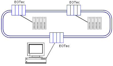
•Two (2) EOTec Fiber Optical Interface Modules
•One (1) EOTec Self-Healing Ring Module
•One (1) EOTec Electrical Interface Modules
•An EOTec Power Supply Module
•ControlNet Single and Dual Self-Healing Rings
Note: In an EOTec 2000 Self-Healing Ring Topology, you can only have one (1) Electrical Interface Module per node. |
|
|
|
|
|

)

