|
Description
The Q438 is a DIN rail mount,
potentiometer input signal condi-
tioner with 1800VDC isolation
between DC power and the input/
output circuitry. The input
provides a constant voltage
and is designed to accept any
three-wire potentiometer from
100 ohms to 100k ohms. The field
configurable output is switch
selectable providing a 0-5V,
0-10V, 0-1mA, 0-20mA or 4-20mA
DC signal. Wide ranging, precision
zero and span pots, used in
conjunction with DIP switches,
allow 80% adjustablity of offset
and gain to transmit a full
scale output from any 20% portion
of the potentiometer input.
Application
The Q438 is useful in transmitting
process control setpoints to
remote PID controllers or interfacing
position or level sensors to
data acquisition and control
systems. The high density DIN
rail mounting offers an extremely
compact solution for saving
valuable panel space.
Configuration
In a valve positioning application
a potentiometer is sometimes
used as a feedback signal. Quite
often a wide open valve is only
a 25% turn of the feedback potentiometer.
The Q438 can easily be adjusted
with the zero and span to provide
a fullscale output signal (e.g.
4-20mA) representing 0-25% or
even 50-75% of the potentiometer
input.
Unless
otherwise specified, the factory
presets the Model Q438 as follows:
|
Input
Range:
|
 |
0
to 100% |
|
Output:
|
|
4
to 20mA |
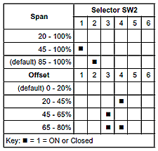
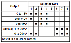
For
other output ranges, refer to
Tables 1 and 2 to reconfigure
switches SW1 and SW2 for the
desired input and output ranges.
WARNING:
Do not change switch settings
with power applied. Severe damage
will result!
Calibration
Note: For best results, calibration
should be performed with the
intended output load, in the
operating environment, mounted
on a DIN rail, allowing at least
one hour for thermal equilibrium
of the system.
1.
With power disconnected, set
the output and input switch
selectors (SW1 and SW2) to the
desired ranges (see Tables 1
and 2).
|
 |
2.
Connect the input to a potentiometer.
Connect the output to the actual
device load (or a load approximately
equivalent to the actual device
load value) and apply power.
Note:
To maximize thermal stability,
final calibration should be
performed in the operating installation,
allowing approximately 1 to
2 hours for warm up and thermal
equilibrium of the system.
3.
Set the input to the desired
minimum and adjust the zero
potentiometer for the desired
minimum output.
4.
Set the input to the desired
maximum and adjust the span
potentiometer for the desired
maximum output.
5.
Repeat steps 3 and 4, if necessary.
Table
1: Input Range Settings

Table
2: Output Range Settings

|