|
Description
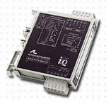
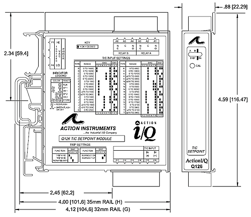
The ActionI/Q model Q126 is
a DIN rail mount, thermocouple
input limit alarm with input
terminal cold junction compensation
(cjc), dual setpoints and two
contact closure outputs. The
field configurable input and
alarm functions offer flexible
setpoint capability. There are
up to six temperature ranges
available for each thermocouple
type to ensure accuracy and
maximize setpoint resolution.
A bipolar input switch is provided
for temperature ranges below
0 C.
The
Q126 is configurable as a single
or dual setpoint alarm, with
HI or LO trips, upscale or downscale
thermocouple burnout detection
and failsafe or non-failsafe
operation. Also included are
adjustable deadbands (up to
100% of full scale input) for
each setpoint and a universal
AC power supply which accepts
any voltage between 85 and 265VAC.
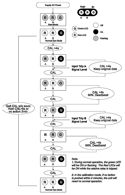
TouchCAL
Technology
Action has simplified setpoint
calibration. Using a pushbutton
instead of potentiometers, improvements
in calibration resolu- tion
and reliability are realized
due to the elimination of the
potentiometer's mechanical variability.
For calibration, the user simply
inputs the signal level of the
desired trip, then presses the
push-button to store it in non-volatile
memory. The deadband, or hysteresis,
level is input next and is stored
with another press of the button.
Diagnostic
LEDS
The Q126 is equipped with three
front panel LEDs. The green
LED is a dual function LED labeled
IN, which indicates line power
and input signal status. Active
AC power is indicated by the
illuminated LED. If this LED
is off, check AC power and wiring
connections. If the input signal
is 7% above or below the configured
input range the green LED will
flash at 8Hz or 4Hz, respectively.
The two red LEDs indicate the
relay state of each setpoint.
An illuminated red LED indicates
the tripped condition for the
respective setpoint.
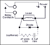
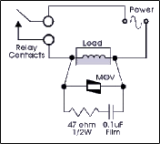
Output
The Q126 is equipped with two
SPDT (form C) relays, rated
at 120VAC or 28VDC at 5 amperes.
Each of these relays is indepen-
dently controlled by the field
configurable setpoint and deadband.
|
 |
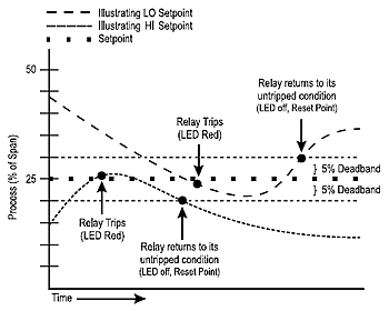
Operation
The Q106 limit alarm setpoints
can be configured for HI or
LO, failsafe or non-failsafe
operation. Each of the setpoints
has a respective HI or LO deadband.
In a tripped condition, the
setpoint is exceeded and the
appropriate red LED will illuminate.
The trip will reset only after
the process falls below the
HI deadband or rises above the
low deadband (see Figure 1).
For proper deadband operation,
the HI setpoint must be set
above the LO setpoint. In failsafe
operation, the relay is energized
when the process is below the
HI setpoint or above the LO
setpoint (opposite for non-
failsafe). In the failsafe mode,
a power failure results in an
alarm state output.
Dynamic
Deadband
Circuitry in the Q106 prevents
false trips by repeatedly sampling
the input. The input must be
beyond the setpoint for 100
milliseconds, uninterrupted,
to qualify as a valid trip condition.
Likewise, the input must fall
outside the deadband and remain
there for 100 milliseconds to
return the alarm to an untripped
condition. This results in a
"dynamic deadband"
-based on time- in addition
to the normal deadband.
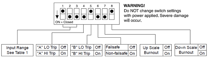
Configuration
Unless otherwise specified,
the factory presets the Model
Q126 as follows:
|
Input:
|
|
Type
J |
|
Range:
|
|
0
to 350 C |
|
Output:
|
|
Dual,
SPDT |
|
Trip:
|
|
A:
HI, B: LO |
|
Failsafe:
|
|
No |
|
Deadband:
|
|
A,
B: 0.25% |
The
AC power input accepts any AC
source between 85 and
265VAC.
Note:
An I/QRail is required to power
the modules. See ordering information.
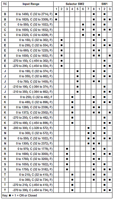
For
other I/O ranges, refer to Table
1 and reconfigure switches
SW1 and SW2 for the desired
input type, range and function.
|